How this project got started and steps to turn the Pi into a temperature sensing device.
The Polar Vortex
In Chicago in early 2019, the temperature dipped down to around -25 F.
I live in a condo building that has an indoor parking garage on the ground floor. One evening, during the Polar Vortex event, the building’s garage door got stuck open.
The building management company had to make an emergency call to a lucky garage door repair guy, who probably charged triple the normal rate, who came out and determined that someone’s garage door opener transmitter was stuck “on”. After determining where the transmitter was and unsticking it, the door closed normally.
There are many exposed water pipes within the garage area and the condo board was concerned about pipes freezing during a similar event.
I’ve regularly attended condo board meetings, and based on some comments I’ve made on various topics, the condo board has identified me as the “technical guy” in the building. So, they asked me for some help in finding a solution that would sense an abnormally low temperature and notify them, via an “app”, that there was a problem.
I looked around the interweb for various solutions. I found that they all have some sort of limitations. Cheaply made, lacking features, requires a monthly subscription to a monitoring web site, etc… Also, IoT (Internet of Things) devices tend to have a bad reputation around security and lack of firmware updates. I didn’t want our garage sensor to become part of a bot net.
I started thinking about the problem more and recalled that I had a Raspberry Pi B+ gathering dust that I’ve been meaning to use for a project for some time.
I have an idea to periodically send temperature readings up to AWS. If the temperature falls below a certain threshold, send a text message to a group of people, indicating the problem. I also want some kind of heartbeat sensor to know if the device stops working.
I can do the temperature sensing and sending the data with the Pi. Let’s review the Pi capabilities and what we need to do to get the data into the cloud.
Here are some specs I grabbed from a site:
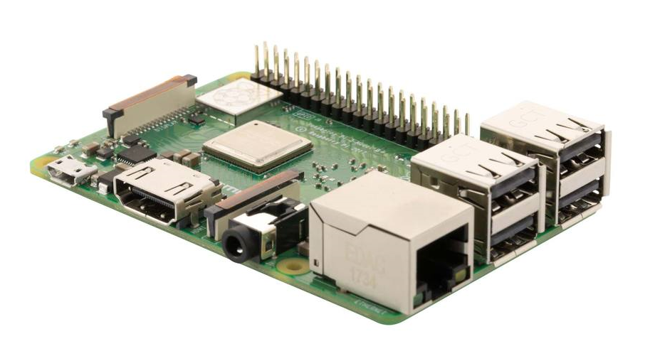
The Raspberry Pi model 3 B+ Specs ($35)
- SOC: Broadcom BCM2837B0, Cortex-A53 (ARMv8) 64-bit SoC
- CPU: 1.4GHz 64-bit quad-core ARM Cortex-A53 CPU
- RAM: 1GB LPDDR2 SDRAM
- WIFI: Dual-band 802.11ac wireless LAN (2.4GHz and 5GHz ) and Bluetooth 4.2
- Ethernet: Gigabit Ethernet over USB 2.0 (max 300 Mbps). Power-over-Ethernet support (with separate PoE HAT). Improved PXE network and USB mass-storage booting.
- Thermal management: Yes
- Video: Yes – VideoCore IV 3D. Full-size HDMI
- Audio: Yes
- USB 2.0: 4 ports
- GPIO: 40-pin
- Power: 5V/2.5A DC power input
- Operating system support: Linux and Unix
This is a very capable small computer that can run just about any linux-based software you can think of. The key feature I needed was the 40-pin GPIO header.
Here’s a somewhat less powerful Raspberry Pi Zero W with a much more attractive price tag:
Specs for the Raspberry Pi Zero W ($10)
- Dimensions: 65mm × 30mm × 5mm
- SoC: Broadcom BCM2835
- CPU: ARM11 running at 1GHz
- RAM: 512MB
- Wireless: 2.4GHz 802.11n wireless LAN
- Bluetooth: Bluetooth Classic 4.1 and Bluetooth LE
- Power: 5V, supplied via micro USB connector
- Video & Audio: 1080P HD video & stereo audio via mini-HDMI connector
- Storage: MicroSD card
- Output: Micro USB
- GPIO: 40-pin GPIO, unpopulated
- Pins: Run mode, unpopulated; RCA composite, unpopulated
- Camera Serial Interface (CSI)
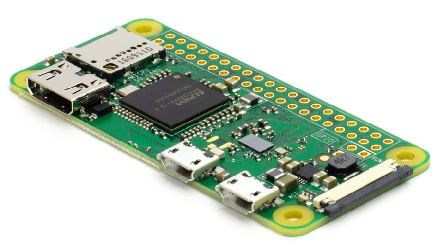
The Pi Zero W is sufficient for my needs and uses less power. The only downside is the GPIO header is unpopulated and I will need to solder one on. But that sounds like a fun project, so why not. I found my Radio Shack soldering pencil from the 90’s, some lead-laden solder, and I’m good to go.
Turning the Pi into a temperature sensor
The ultimate goal of the project is to turn the Pi into a temperature sensor that can periodically send the temperature reading to the cloud. The first step is to create a circuit that includes a digital temperature sensor. There are plenty of blog posting around on how to do this. It’s one notch in complexity above a blinking LED light. You can get digital temperature sensors from Amazon for 5 for $10 shipped. Other than that, just need a small breadboard for prototyping and some jumper wires.
I won’t go into detail on the circuit, as I mentioned, there are many blog postings on that. Here’s the detail on the circuit (from the linked blog post):
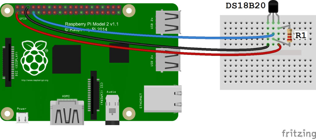
The prototype ended up looking like this, ugly but it works:
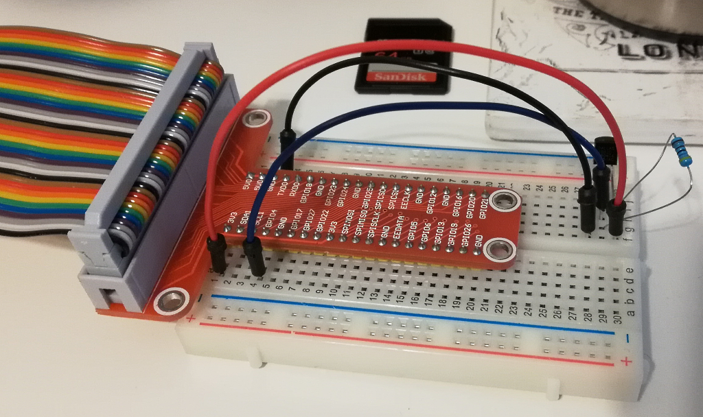
The other end of the ribbon cable is connected to the GPIO port of the Pi (B+ in this case, but doesn’t matter).
When I started this project, I assumed I would have to do some low-level programming to access the GPIO pins. You do in the case of the blinking LED, for example. In this case, the Pi knows about the digital temperature sensor. You can load some drivers and the Pi will continually take readings and write them to a logical file on the Pi file system. From a programming perspective, you merely have to read and parse a small text file. Very easy.
Here’s a sample of what the text looks like:
3c 01 4b 46 7f ff 0c 10 36 : crc=36 YES
3c 01 4b 46 7f ff 0c 10 36 t=19750
The “t=19750” is the current temperature in Celsius * 1000. Or 19.75 C or about 67 F.
To setup the driver to read the temperature sensor, do the following steps:
Do “sudo nano /boot/config/txt” and add a line at the end of the file (without quotes), “dtoverlay=w1-gpio,gpiopin=4”.
Do “sudo nano /etc/modules” and add two lines to the end of the file (without quotes), “w1-gpio” and “w1-therm”.
Reboot the Pi. Do a quick check to see if it’s working:
Change to the folder /sys/bus/w1/devices. In that folder, there will be a folder called “28-*“, change to that folder. In that folder “cat w1-slave” to see the thermometer reading.
In the next post, I will review the code to parse the text file (from the blog post above) and send the data up to AWS for processing.